
Train Cab Signal System.
Personal traffic light.

The Cab Signal System is one of the fundamental elements of the modern, safely functioning railroad. It ensures proper spacing between trains and constantly monitors trains ensuring that the operators (engineers) obey appropriate train speed restrictions. Despite the fact that it was originally developed in the early 1920’s it withstood the test of time and is still very relevant in the today’s world.
What is a Cab Signal System?
In its most basic form, the Cab Signal System is a box inside a cab of the locomotive, cab car (passenger car with a locomotive control stand) or motored unit (MU). It displays a variety of aspects (aka signals akin to traffic lights) for the engineer to see. Each aspect has a particular well defined meaning in terms of the maximum speed. It also contains an acknowledgement system which ensures that the train engineer physically acknowledges each change in aspect (by either actuating a knob or some type of pedal) and slows down if needed. Lack of acknowledgement and exceeding the speed limit will cause automatic train brake application ensuring safe stop of the train. Cab signal system performing this function is typically referred to as Automatic Train Control (ATC), because of its ability to bring a train to a complete stop through penalty brake application.
Foundation of Cab Signal System
The modern Cab Signal System typically found in the United States is based on the system developed by the Pennsylvania Railroad and Union Switch Signal. It relies on the wayside’s signal system to supply it with the appropriate information. While the signal system itself is also a very fascinating topic (for future articles), in its most rudimentary form it splits railroad track into a number of blocks/sections. The block train is in and conditions in front of it, determines what aspect/signal is displayed to the operator. The system communicates to the locomotive (or cab car) via running rail, by encoding the message as a pulsating signal (with different pulsating frequency corresponding to different aspects/signals) on a carrier signal. It is typically a 100Hz AC carrier signal with on/off pulses added on it by a dedicated pulse relay. The system is designed to be continuous and fail safe, meaning there is continuously a carrier signal present on the running rail and lack of signal is a stop signal (aka fail safe condition). Note that this also means that the cab signal will be lost if the rail is broken.
Cab signal implementation
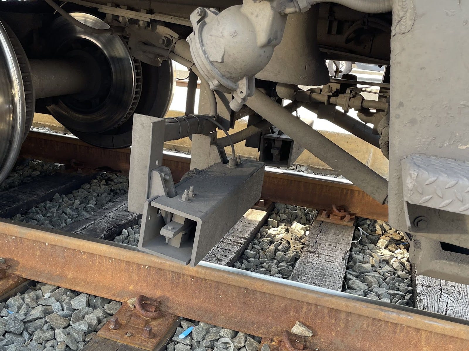
On the equipment side, the cab signal system is implemented through a pair of onboard receiver coils which read the signal from the running rails, process it and display it to the operator on the Aspect Display Unit (ADU).
Original implementation of the ADU was literally a “mirror image” of the signals seen along the track. For example, the system shown below is a four aspect system corresponding to the four possible cab signals. For this discussion we assume 100Hz carrier frequency. Note the exact implementation can vary and this is just an example based on the Pennsylvania Railroad legacy system.
Starting from the top:
Clear signal - 100Hz carrier with 180 pulses per minute - maximum track speed (typically 60 or 80 mph)
Approach Medium - 100Hz carrier with 120 pulses per minute - 45 mph max track speed
Approach - 100Hz carrier with 75 pulses per minute - 35 mph max track speed
Restricting - 100Hz carrier without pulses - 20 mph max track speed
Stop - this is not an aspect signal rather its absence of carrier frequency (which is present in the other four).

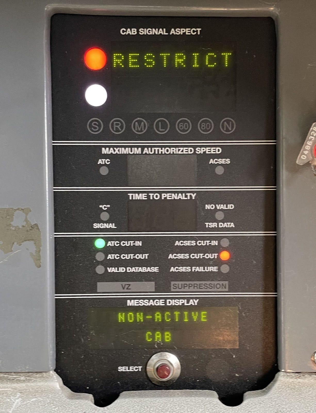
As cab signal system evolved it was also supplemented with additional systems such as Positive Train Control (PTC). To support these developments ADUs evolved as well and are now part of the more complex package (such as the one shown below). For example, Amtrak expanded its cab signal system beyond the original 4 aspect system to facilitate higher speed train movement (such as Acela service) and operations in a more congested train environment (requiring smaller block sizes). New cab signal system is a 9 aspect system due to addition of 250Hz carrier frequency and 270 pulses per minute code option.
This enhanced system utilizes both 100Hz and 250Hz carrier frequencies simultaneously with the following pulses per minute: 270, 180, 120 and 75 (see illustration below for exact details). Note the beauty of this system is that if a 4 aspect capable system enters 9 aspect territory it just sees the original 4 aspect system, since a 250Hz carrier is “invisible” to it.

PTC + ATC
Positive train control is another system (to be covered in the future articles) which sits along with the modern cab signal system (or ATC) in the modern locomotives/cab cars. Like cab signal system, it controls the track speed but unlike cab signal system it utilizes constant radio communication with transponders and centralized train control to obtain required information regarding allowable speed. It addresses shortcomings of the ATC system, such as speed around the track curves, by providing more precise (in terms of location along the track) speed limits. Both systems are independent of each other and the most restricting one (in terms of speed) takes priority in the speed enforcement. Note Amtrak’s implementation of the PTC system is referred to as Advanced Civil Speed Enforcement System (ACSES).
Relevant railroad accident
This accident was at a low speed and a good demonstration of the shortcomings of the cab signal system just by itself. LIRR train was operating at the proper track speed of 15 mph (not exceeding it) as dictated by the ATC system as it was approaching Atlantic Terminal. Because the engineer maintained appropriate speed and failed to completely stop, the train hit the platform causing extensive damage and injuries. As eluded to in the discussions above ATC system is unable to stop the train unless speed limited is exceeded, hence the use of additional systems (like PTC). NTSB investigation report

Relevant Standards for further reference
CFR Part 236 - covers standards and instructions for installation, maintenance and repair of signal and train control systems
NORAC Operating Rules - covers signal and operating rules for the railroad